FAQ - 12V Transformers and LED Compatibility
When considering LED retrofit options for MR16/GU5.3 halogen downlights, the buyer should factor in not only light quality but transformer compatibility as well. Replacing your existing 12VAC transformers in addition to your downlights can be costly and inconvenient, making it important that replacement LED downlights work well with your existing installation. The likelihood of compatibility between a 12V LED light and a 12VAC halogen transformer depends on a few factors:
- The type of transformer (Electronic vs. Magnetic vs. LED Driver)
Magnetic transformers will generally work with all MR16 LED lights, albeit at the cost of efficiency and extra power consumption as was explored in this FAQ article. 'LED drivers' are electronic DC power regulators designed specifically for DC LED lighting. They are not suitable for 12VAC (halogen or LED retrofit) lighting. The fundamental difference between LED driver and 12VAC electronic transformer outputs can be found further down the page.
- If the transformer is electronic, it's particular power supply circuitry and load requirements
Electronic 12VAC halogen transformers can vary significantly in design and consequently in how they respond (or do not respond) to different loads.
- The LED light
MR16 LED lights vary in complexity across manufacturers and model designs. The most basic 12V retrofit LED downlight will include the DC LED chips for the light source, and a bridge rectifier composed of diodes to deliver DC to the LEDs from the AC transformer supply. Some LED lights, such as the DR450 by Brightgreen and the 10W Philips Master, have additional modules that intentionally alter the load seen by the transformer to better replicate the load characteristics of 12VAC halogens and thus ensure broader (but not necessarily universal) compatibility with electronic transformers.
Experiment Outline
The output waveform of several electronic transformers for 12VAC MR16 lighting was measured using a Tektronix DPO2012B oscilloscope. A sample of LED lights was used on each transformer to assess it's compatibility and output quality when handling different loads. No dimmers were used in the test circuit.
The electronic transformers tested were: Tridonic Atco Possum, PoweRun Model No. 410-60, OSRAM Redback and a Tridonic Atco speedy. Their specified load requirements were 0.1-0.3 A, 20-60 W, 20-60W and 0.1-0.3 A, respectively. An Atco TM50-2 wire wound transformer was used for comparison. The primary winding for each transformer was connected to 246 (nominally 230) VAC mains, operating at 50 Hz.
35W Halogen Downlight
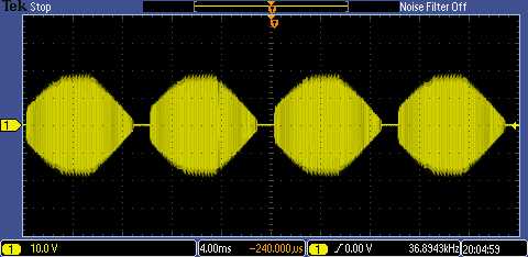
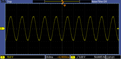
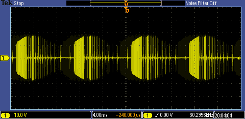
The transformers' output voltage waveforms when powering a 35W Osram Halogen can be seen in the figures below. The load input of the wirewound transformer can be seen to be a simple 50 Hz sine wave. In contrast, the electronic transformers output a high frequency switching signal ranging from approximately 37 kHz to 79 kHz, enveloped within a 100 Hz waveform. Despite the differences in the voltage waveform, all five transformers successfully powered the 35W Halogen light with no perceptible flicker or obvious difference in light output.
Figure 1(a) Wirewound voltage output: 50 Hz sine wave
Power consumption: 46 W
Power factor: 0.87

Figure 1(b)ATCO TM50-2 Wirewound Transformer
Figure 1(c) Possum voltage output: 79 kHz switching, 100 Hz envelope
Power consumption: 37.4 W
Power factor: 0.99

Figure 1(d) Atco Possum Electronic Transformer
Figure 1(e) PoweRun voltage output: 40 kHz switching, 100 Hz envelope
Power consumption: 36 W
Power factor: 0.98
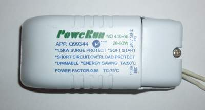
Figure 1(f) PoweRun Electronic Transformer
Figure 1(g) Redback voltage output: 37 kHz switching, 100 Hz envelope
Power consumption: 37.8 W
Power factor: 1.0

Figure 1(h) Osram Redback Electronic Transformer
Figure 1(i) Speedy voltage output: 75 kHz switching, 100 Hz envelope
Power consumption: 37.9 W
Power factor: 0.99
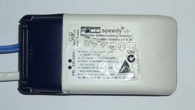
Figure 1(j) Atco speedy Electronic Transformer
LED Testing
Three LED lights from different manufacturers were tested on each transformer including a Brightgreen DR450 7W Retrofit downlight, a 10W Philips Master LED, and a Lucci LEDlux 6W LED. The switching frequencies and switching waveforms of the electronic transformers when supplying identical loads varied greatly, however while power losses do tend to increase with an increase in switching frequency, the power consumed across transformers given the same load varied little (within ± 0.2 W). The power losses as a direct consequence of increased switching frequency can therefore be viewed as negligible. When erratic disruptions in the waveform were observed for a light/transformer combination, this usually coincided with noticeable flicker.
Brightgreen DR450 7W Retrofit Downlight
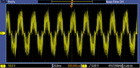
Figure 2(a) Wirewound voltage output: 410 kHz switching about 50 Hz sine wave
Wirewound Transformer
Power consumption: 13.1 W
Power factor: 0.38
Figure 2(b) Possum voltage output: 182 kHz switching, 100 Hz envelope
Possum Electronic Transformer
Power consumption: 7.4 W
Power factor: 0.99
Light output: 399 lm
Figure 2(c) PoweRun voltage output: 65 kHz switching, 100 Hz envelope
PoweRun Electronic Transformer
Power consumption: 7 W
Power factor: 0.98
The high frequency switching cycles are seen to stop and resume at irregular times within the 100 Hz wave envelope. This manifested as visible light flicker and dim light output (dimmed to 0 lm after approximately 10 minutes).
Figure 2(d) Redback voltage output: 75 kHz switching, 100 Hz envelope
Redback Electronic Transformer
Power consumption: 7.6 W
Power factor: 0.96
Light output: 406 lm
Figure 2(e) Speedy voltage output: 167 kHz switching, 100 Hz envelope
speedy Electronic Transformer
Power consumption: 7.5 W
Power factor: 0.98
10W Philips Master LED
Like the DR450, this LED was designed specifically as a retrofit option. It utilises a 'unique, patented, electronic solution'1 to guarantee compatibility with a range of standard 12VAC Halogen electronic transformers.
Figure 3(a) Wirewound voltage output: 231 kHz switching about 50 Hz sine wave
Wirewound Transformer
Power consumption: 17 W
Power factor: 0.47
Figure 3(b) Possum voltage output: 135 kHz switching, 100 Hz envelope
Possum Electronic Transformer
Power consumption: 11.3 W
Power factor: 0.99
Light output: 395 lm
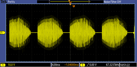
Figure 3(c) PoweRun voltage output: 67 kHz switching, 100 Hz envelope
PoweRun Electronic Transformer
Power consumption: 12.6 W
Power factor: 0.98
Light outpu: 399 lm
Figure 3(d) Redback voltage output: 57 kHz switching, 100 Hz envelope
Redback Electronic Transformer
Power consumption: 11.4 W
Power factor: 0.98
Light output: 394 lm
Figure 3(e) Speedy voltage output: 136 kHz switching, 100 Hz envelope
speedy Electronic Transformer
Power consumption: 11.3 W
Power factor: 0.99
Lucci LEDlux 6W LED
The LED failed to turn on when supplied using the Possum or speedy electronic transformers. Based on the voltage outputs of these transformers taken above, they are likely to have very similar internals and consequently similar responses to identical loads. Both transformers specify a minimum load requirement of 0.1 A. Unlike the 7W DR450 and the 10W Philips Master LEDs, the Lucci LEDlux 6W LED does not 'simulate' the load characteristics of a halogen, resulting in it not being 'recognised' by the transformer.
Figure 4(a) Wirewound voltage output: 50 Hz sine wave
Wirewound Transformer
Power consumption: 11.5 W
Power factor: 0.34
Figure 4(b) PoweRun voltage output: 10 kHz switching, 100 Hz envelope
PoweRun Electronic Transformer
Power consumption: 4.4 W
Power factor: 0.47
Very heavy flickering was observed.
High Frequency Switching Waveforms
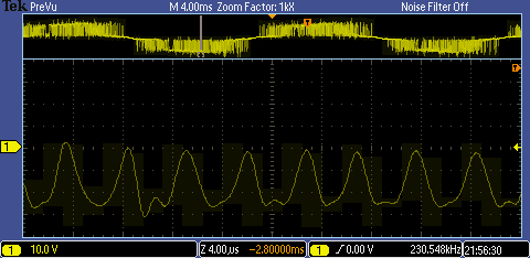
Close-ups of the switching waveforms generated by different transformers is provided in the following figures. The variation in the switching waveform across transformer types can be seen in figures 5b-d.
Figure 5(a) High frequency 37 kHz switching: Halogen + Redback Transformer
Figure 5(b) High frequency 134 kHz switching: Philips Master + Possum Transformer
Figure 5(c) High frequency 57 kHz switching: Philips Master + Redback Transformer
Figure 5(d) High frequency 231 kHz oscillation: Philips Master + Wirewound Transformer
12VAC Electronic Transformers and LED Drivers
LED drivers and electronic transformers for retrofit LED lighting are not interchangeable. They differ in output and load compatibility i.e. which LED lights they will work with. The fundamental difference between the two is that LED drivers output DC while electronic halogen transformers output 12VAC. The difference in their voltage outputs can be seen in figure 6. The yellow voltage signal is that supplied by a Redback electronic transformer to a Philips retrofit LED light. It oscillates about 0V, regularly switching polarity with a measured output of 11.9VAC. The white voltage signal is that supplied by a LED driver by Brightgreen to their D900 Curve LED downlight. The voltage is approximately 36.5V (oscillating slightly on account of voltage ripple from the 50 Hz mains) DC.
Figure 6. LED Driver (white) and 12VAC Electronic Transformer (yellow) outputs
The DC output of LED drivers has the advantage of practically eliminating voltage drop and reducing radiated RFI.
Related Pages
- Magnetic vs. Electronics Transformers for MR16 LEDs
- What makes a good incandescent/halogen replacement?
- Are LED lights dimmable?
Back to FAQ index


