FAQ - How we test LED lights
Background Theory
Light sources can be evaluated based on several photometric characteristics including luminous flux, luminous intensity, and spectral distribution. Luminous flux (measured in lumens) is the total light output of a source and is the fundamental photometric quantity from which other quantities such as luminous intensity are defined in terms of. The spectral distribution or spectral composition details the relative quantity of each wavelength, or color, that a light source is composed of.
Test Setup
Values for the luminous flux of each LED product are obtained by measuring luminous intensity distribution using a Type C goniophotometer¹. The goniophotometer is comprised of a photometer mounted on a motor-driven arm that rotates in plane and at a fixed distance relative to the light source being tested. Lux (lm/m²) values at each angular step are logged into our custom application in synchronization with the motor actuation.
The scanning resolution of our test setup is a 1.8° longitudinal (vertical) and 90° lateral (horizontal) grid. The fine angle resolution in the vertical plane was used to minimize the impact of any non-systematic measurement error by calculating over a large data set. A 90° lateral resolution was sufficient for testing luminaires designed to provide symmetrical distribution. As our testing is focused on indoor LED light fixtures, light is generally emitted in the forward direction and no light emission was blocked by the test apparatus. To avoid ambient light and temperature variation effecting the results, the test was conducted in a dark and temperature controlled room.
The goniophotometer thus allows us to measure the light output of an LED along a circumferential area on two transverse planes. A process of interpolation and integration based on our measurements is calculated, from which the total light output over a spherical surface area, independent of measuring distance, i.e. the luminous flux is obtained. Note: that only one of the two axis are show in the video and the video is sped up 256 times.
Power Supplies
220-240 VAC light fittings are powered directly from an (Australian standard) AC wall socket. 110-120 VAC lights are supplied from a 240 - 115V Isolated Stepdown Transformer. The standard light fitting mounted on our goniophotometer is a bayonet fitting. Bulbs with non-B22 fittings are connected via B22 base adaptors.
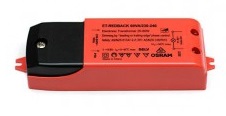 All MR16 lights are connected directly to an OSRAM Redback 20-60 Watt electronic transformer via standard cables approximately 240 mm in length so as to minimise voltage drop from the 12 VAC transformer output. The OSRAM Redback transformer was selected as the standard transformer for our test procedure based on it's popular use in Australian homes and the assumption that the user would wish to minimise cost by retrofitting LED lights to their existing halogen transformer rather than pay the additional cost for a specific transformer recommended by the LED light manufacturer. It should therefore be noted that the measurements gathered for all MR16 lights is specific to the electronic transformer used and performance may vary using other transformers.
The same power supply configurations were used to test lumen output, intensity distribution, wattage, power factor, temperature and dimming.
Dimmers
Products claiming to be dimmable were subjected to dimming tests that measure the range and gradation in brightness along ten evenly spaced dimming positions. 240V and 12V lights were tested on either a Clipsal 32E450UDM Universal Dimmer or a HPM CAT250L Leading Edge Dimmer, depending on the compatible dimmer type claimed by the manufacturer. 120V dimmable lights were tested using a Lutron Skylark CTCL-153P CFL/LED Dimmer.
Equipment
Lux light meter
|
Spectrum data #1
|
Thermal images
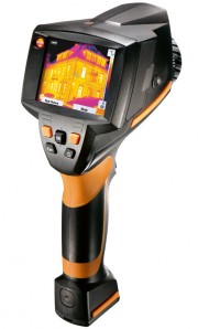
Thermal images and temperature were taken using a Testo 875 thermal imager. The unit has 160 x 120 pixels, a thermal sensitivity of < 80 mK and 32° standard lens. |
Power measurement #1
|
Spectrum data #2
|
Spectrum Analyzer
|
Microcontroller
|
Power Measurement #2
|
Voltage Measurement
|
Flicker Measurement
A technical explanation of the results obtained from our flicker measurements can be found on the FAQ page How do we measure flicker?. |
Related Pages
References
1Goniophotometer type that maintains the burning position unchanged with respect to gravity specified in IES LM-79-08 Approved Method: Electrical and Photometric Measurements of Solid-State Lighting Products
Back to FAQ index
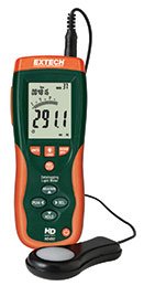 The equipment used in our goniophotometer test rig include an Extech HD450 Data Logging Light Meter with a USB interface back to a PC.
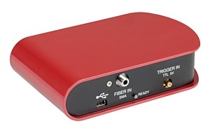 Initially the Thorlabs CCS100 CCD Spectrometer measured the spectral composition of the light source using a fiber optic cable mounted directly below the test product. Calibration issues resulted in switching to the UPRtek MK350 unit later on for color data.
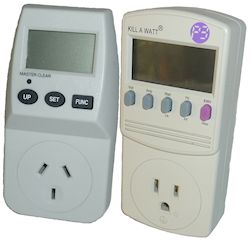 Wattage, voltage and power factor were (initially) measured using a Mains Power Meter. These meters were found to be too inaccurate however and all measurements are now
being done with the Cabac CCI meter (see below).
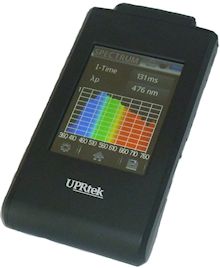 UPRtek MK350 Spectrometer was used for color measurements (CCT & CRI).
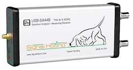 SignalHound USB SA44B Spectrum Analyzer for radio interference measurements (plus a collection of antennas).
 Freescale Kinetis L series microcontroller and custom PCB which is used to control the 1.8° stepper motor, which is attached to the rotating arm of the goniophotometer. The Microcontroller has a USB interface and is in turn controlled from a laptop PC.
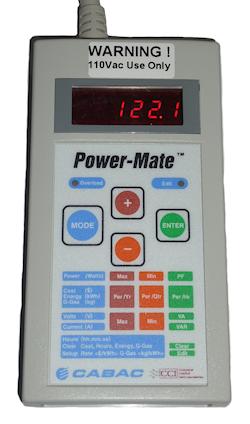 Wattage, voltage and power factor were measured using a Cabac CCI Powermate power meter. Two different variants are used, one for 240V and one for 110V measurements. Claimed accuracy is 0.2% with a voltage and current sample rate of 4800 / sec.
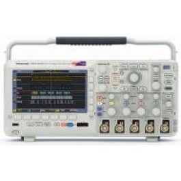 Transformer and driver voltage outputs were measured using a Tektronix DPO2012b 100 MHz Digital Storage Oscilloscope and a TPP0200 200 MHz, 10x passive probe.The DPO2012b claims 100 MHz
bandwidth, 1 GS/s sample rate and a record length of 1 Mpoints.
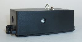 Light flicker was measured using a TSL257 high sensitivity light to voltage converter IC paired with a DPO2012b Oscilloscope to capture it's output waveform.
The TSL257 IC by TAOS consists of a photodiode, operational amplifier and feedback components for low noise outputs and high frequency switching capability.